Objective 2.1: Compare and Contrast the Benefits of Running VMware NSX on Physical Network Fabrics Fabrics
Differentiate physical network topologies – Note about leaf-spine architecture
With Leaf-Spine configurations, all devices are exactly the same number of segments away and contain a predictable and consistent amount of delay or latency for traveling information. This is possible because of the new topology design that has only two layers, the Leaf layer and Spine layer.
The Leaf layer consists of access switches that connect to devices like servers, firewalls, load balancers, and edge routers.
The Spine layer is the backbone of the network, where every Leaf switch is interconnected with each and every Spine switch.
The standard network data center topology was a three-layer architecture:
- the access layer, where users connect to the network;
- the aggregation layer, where access switches intersect;
- and the core, where aggregation switches interconnect to each other and to networks outside of the data center.
The design of this model provides a predictable foundation for a data center network:
- Physically scaling the three-layer model involves identifying port density requirements and purchasing an appropriate number of switches for each layer.
- Structured cabling requirements are also predictable, as interconnecting between layers is done the same way across the data center.
- growing a three-layer network is as simple as ordering more switches and running more cable against well-known capital and operational cost numbers.
The 3 Tiered topology ( composed by Core-Aggregation-Access) could be inefficient in a datacenter context: problem with bottleneck occurred by Eest-West traffic, non-linear scaling in terms of performance and costs and not completing consumption of the available network resources, has been favored the adoption of the leaf-spine network topology.
Talking more about East-West traffic, network segments are spread across multiple switches requiring hosts to travers networks interconnection. The huge growth of this traffic is given by the adoption of converged (or hyperconverged) systems and the virtualization, that simply increase the host density per host and rack and requires more and more bandwidth performing management activities (like DRS, backup) or simply increase performance for software defined storage systems that are “walking” with virtualized systems (like storage virtualization like vSAN)
A leaf-spine design scales horizontally through the addition of spine switches, which spanning-tree deployments with a traditional three-layer design cannot do. This is similar to the traditional three-layer design, just with more switches in the spine layer. In a leaf-spine topology, all links are used to forward traffic, often using modern spanning-tree protocol replacements such as Transparent Interconnection of Lots of Links (TRILL) or Shortest Path Bridging (SPB). TRILL and SPB provide forwarding across all available links, while still maintaining a loop-free network topology, similar to routed networks.
Advantages:
- All East-West traffic are equidistant
- Uses all interconnection links
- supports fixed configuration switches –> Leaf-spine allows for interconnections to be spread across a large number of spine switches, obviating the need for massive chassis switches in some leaf-spine designs.
Cons:
- A spine can only extend to a certain point before either the spine switches are out of ports and unable to interconnect more leaf switches, or the oversubscription rate between the leaf and spine layers is unacceptable
- Leaf-spine networks also have significant cabling requirements
- Interconnecting switches dozens of meters apart requires expensive optical modules, adding to the overall cost of a leaf-spine deployment
Source: http://searchdatacenter.techtarget.com/feature/The-case-for-a-leaf-spine-data-center-topology
Differentiate virtual network topologies and Given a specific physical topology, determine what challenges could be addressed by a VMware NSX implementation.
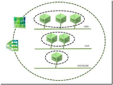
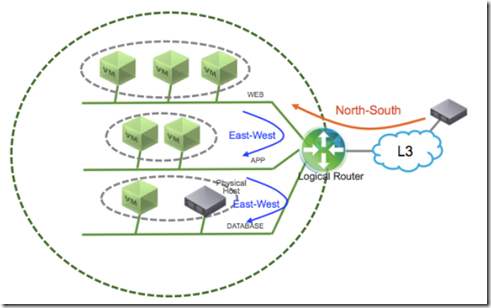
A typical multi-tier application architecture is composed by database tier, application tier and presentation/web tier. All tier must be protected against networks attacks and could be assisted by load-balancer and/or VPN as well. Every network segments which provide network connection between VMs in the same tier must be “isolated”.
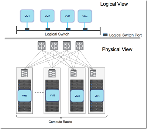
The logical switching capability in the NSX platform provides the ability to spin up isolated logical L2 networks with the same flexibility and agility that exists virtual machines.
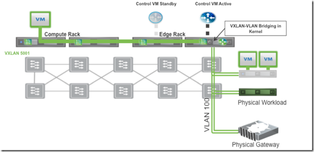
Endpoints, both virtual and physical, can connect to logical segments and establish connectivity independently from their physical location in the data center network.
When utilized in conjunction with the multi-tier application previously discussed, logical switching allows creation of distinct L2 segments mapped to the different workload tiers, supporting both virtual machines and physical hosts.
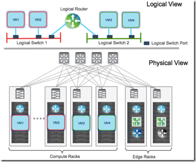
The logical routing capability in the NSX platform provides the ability to interconnect both virtual and physical endpoints deployed in different logical L2 networks.
The deployment of logical routing can serve two purposes:
- interconnecting endpoints – logical or physical – belonging to separate logical L2 domains
- interconnecting endpoints belonging to logical L2 domains with devices deployed in the external L3 physical infrastructure
OSPF End-to-End Connectivity –> ECMP
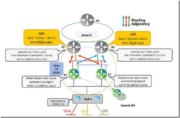
The gray routers R1 and R2 can represent either L3-capable ToR/EoR switches that serve as ABRs and are connected to the datacenter backbone OSPF area 0, or L3-capable switches positioned at the aggregation layer of a traditional pod-based datacenter network architecture that serve as the L2/L3 demarcation point. ESG1, ESG2 and DLR-1 are in the same NSSA area 52.
Route Advertisement for North-to-South Traffic:
- DLR-1 redistributes its connected interfaces (i.e., logical networks) into OSPF as type 7 LSAs. This provides immediate availability inside this area as well as for other non-stub areas
- ESG1 and ESG2 each have a static route pointing to DLR that summarizes the entire logical switch IP address space
- With the static route or routes representing the logical network address space, the requirement of redistributing the logical network connected to DLR can be eliminated
- This is essential for maintaining the reachability of NSX logical networks during active control VM failure with aggressive timers in an ECMP-based design
- These routes will reach R1 and R2 as type 7 LSAs where they will be translated into type 5 LSAs
- If further optimization with area summarization is desired, it is recommended that only the summary route injected by ESG1 and ESG2 is translated and propagated into other areas
Route Advertisement for South-To-North Traffic:
- Providing a default route to the NSX domain is necessary so that NSX can reach the ABR without sending entire routing table to Edge and DLR
- In this design R1 and R2 are the ABRs. They inject the default route into the NSSA area; neither ESG1/ESG2 nor DLR-1 generate it
- It is important to confirm that R1 and R2 do not push a default route towards ESGs if they get disconnected from the OSPF backbone area 0
- If R1/R2 keep generating the default route without an active connection towards area 0, it is important to ensure a direct path between R1 and R2 exists and can be leveraged whichever is disconnected from area 0
BGP and NSX Connectivity Options
BGP is becoming a preferred protocol in modern data center spine-leaf topology. The concept of BGP as protocol to interconnect autonomous system applies well when considering NSX as separate autonomous routing zone with its own internal routing supporting east-west forwarding. It’s highly recommended for ESG and DLR in these situations:
- It is advantageous to avoid the complexity of OSPF area design choices
- NSX is considered separate autonomous area
- Top-of-rack is part of an existing L3 BGP Fabric
- Better route control is required
- Multi-tenant design is required
NSX supports:
- eBGP: typically used when exchanging routes with physical networks
- iBGP: between DLR and ESG within the NSX domain
Keep in mind when planning the ASN (numbering schema):
- NSX currently supports only 2-byte ASN –> use private ASN for NSX tenants (RFC 6996) –> 64512-65534 inclusive
- ASN 65535 is reserved (RFC 4271)
- it is possible to reuse the same BGP ASN if the physical router devices support BGP configuration capabilities such as “neighbor <ip address> allowas-in <occurrences>” and “neighbor <ip address> as-override”.
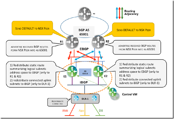
For the multi-tenant design with BGP, a summary route for the NSX tenant’s logical networks is advertised from the ESGs to the physical routers through an EBGP session.
Route Advertisement for North-to-South Traffic:
- DLR-1 injects into iBGP the connected logical subnets address space
- ESG1 and ESG2 both have a static route summarizing the whole logical address subnet space pointing to DLR-1
- This route is injected into BGP and using BGP neighbor-filtering capabilities and is advertised only to R1 and R2 via EBGP
- The static routes representing entire NSX logical network space provide the following advantages:
- Reducing the configuration burden of advertising new logical networks introduced via automation.
- Avoiding routing churn caused by each new advertisement.
- Maintaining reachability of NSX logical networks during control VM failure with aggressive timers in ECMP based design. It is not required for an ESG active-standby, stateful services design where aggressive timers are not used.
Route Advertisement for South-To-North Traffic:
- To reach any destination outside its own AS, the DLR follows the default route. –> This is derived either from backbone/core routers or advertised via “network 0.0.0.0” command by respective BGP peers when 0/0 is present in the routing table
- In eBGP/iBGP route exchange, when a route is advertised into iBGP, the next hop is carried unchanged into the iBGP domain
- To avoid external route reachability issues, the BGP next-hop-self feature or redistribution of a connected interface from which the next hop is learned is required.
- Usually an iBGP domain calls for a full mesh of iBGP sessions between all the participant routers.
Differentiate physical/virtual QoS implementation
Virtualized environments must carry various types of traffic, Each traffic type has different characteristics and applies different demands on the physical switching infrastructure. The cloud operator might be offering various levels of service for tenants. Different tenants’ traffic carries different quality of service (QoS) values across the fabric. No reclassification is necessary at the server-facing port of a leaf switch. If there were a congestion point in the physical switching infrastructure, the QoS values would be evaluated to determine how traffic should be sequenced – and potentially dropped – or prioritized.
Two types of QoS configuration supported in the physical switching:
- handled at L2 (QoS)
- at the L3 or IP layer (DSCP marking)
NSX allows for trusting the DSCP marking originally applied by a virtual machine or explicitly modifying and setting the DSCP value at the logical switch level –> the DSCP value is then propagated to the outer IP header of VXLAN encapsulated frames.
For virtualized environments, the hypervisor presents a trusted boundary, setting the respective QoS values for the different traffic types.
Differentiate single/multiple vSphere Distributed Switch (vDS)/Distributed Logical Router implementations
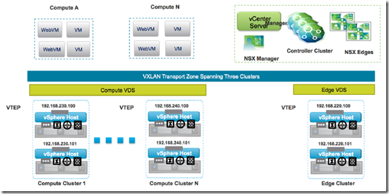
The vSphere Virtual Distributed Switch (VDS) is a foundational component in creating VXLAN logical segments. The span of VXLAN logical switches is governed by the definition of a Transport Zone –> each logical switch can span across separate VDS instances over the entire transport zone.
Advantages in keeping separate VDS for compute and edge:
- Flexibility in span of operational control –> Compute/virtual infrastructure administration and network administration are often separated groups and tasks, accesses and capacities are different
- Flexibility in managing uplink connectivity on computes and edge clusters
- The VDS boundary is typically aligned with the transport zone, allowing VMs connected to logical switches to span the transport zone
- Flexibility in managing VTEP configuration
- Avoid exposing VLAN-backed port groups used by the services deployed in the edge racks (e.g., NSX L3 routing and NSX L2 bridging) to the compute racks, thus enabling repeatable streamlined configuration for the compute rack
The general design criteria used for connecting ESXi hosts to the ToR switches for each type of rack takes into consideration:
- The type of traffic carried – VXLAN, vMotion, management, storage
- Type of isolation required based on traffic SLA
- Type of cluster – compute workloads, edge, and management either with or without storage
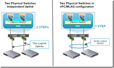
- The amount of bandwidth required for VXLAN traffic –> single vs multiple VTEP
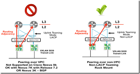
- Simplicity of configuration – LACP vs. non-LACP
- Convergence and uplink utilization factors
vDS Uplink Teaming options for NSX:
- Route based on originating Port
- NSX supported
- Multi-VTEP supported
- 2 Active Uplink
- Route based on MAC Hash
- NSX supported
- Multi-VTEP supported
- 2 Active Uplink
- LACP
- NSX supported
- Multi-VTEP Not supported supported
- Active uplink flow based
- Route based on IP Hash (Static Eth Channel)
- NSX supported
- Multi-VTEP Not supported supported
- Active uplink flow based
- Explicit Failover Order
- NSX supported
- Multi-VTEP Not supported supported
- Only one link active
- Route based on Physical NIC Load (LBT)
- NSX not supported
Additional teaming options considerations:
- Every port-group defined as part of a VDS could make use of a different teaming option –> depending on requirements of associated traffic
- Teaming option associated to a given port-group must be the same for all the ESXi hosts connected to that specific VDS, even if they belong to separate clusters
- LACP or static EtherChannel –> the same option should be used for all the other port-groups/traffic types defined on the VDS
- The VTEP design impacts the uplink selection choice since NSX supports single or multiple VTEPs configurations
- Since the single VTEP is only associated in one uplink in a non port-channel teaming mode, the bandwidth for VXLAN is constrained by the physical NIC speed.
- The number of provisioned VTEPs always matches the number of physical VDS uplinks
- The recommended teaming mode for the ESXi hosts in edge clusters is “route based on originating port” while avoiding the LACP or static EtherChannel option
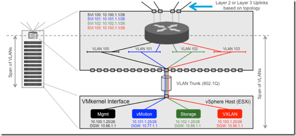
When deploying a routed data center fabric, each VLAN terminates at the leaf switch (i.e., Top-of-Rack device), so the leaf switch will provide an L3 interface for each VLAN. Such interfaces are also known as SVIs or RVIs.
VXLAN Traffic: After the vSphere hosts have been prepared for network virtualization using VXLAN, a new traffic type is enabled on the hosts. Virtual machines connected to one of the VXLAN-based logical L2 networks use this traffic type to communicate. The VXLAN Tunnel Endpoint (VTEP) IP address associated with a VMkernel interface is used to transport the frame across the fabric.
Management Traffic: is sourced and terminated by the management VMkernel interface on the host. It includes the communication between vCenter Server and hosts as well as communication with other management tools such as NSX manager.
vMotion traffic: is used to move this virtual machine state. Each vSphere vMotion VMkernel interface on the host is assigned an IP address. Depending on the speed of the physical NIC, the number of simultaneous virtual machine vSphere vMotion migrations is decided.
Storage traffic: is used to provide features such as shared or non-directly attached storage (NAS, iSCSI). This subnet cannot span beyond this leaf switch, therefore the storage VMkernel interface IP of a host in a different rack is in a different subnet.
Host Profiles for vmk ip addressing: After this host has been identified and basic configured has been performed, a host profile can be created from that host and applied across the other hosts in the deployment. The following are among the configurations required per host:
Differentiate NSX Edge High Availability (HA)/Scale-out implementations
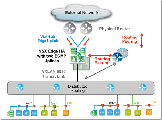
The NSX Edge services gateway can be configured in two modes – active-standby services mode or ECMP
- Active/Standby Mode – Stateful Edge Services: is the redundancy model where a pair of NSX Edge Services Gateways is deployed for each DLR
- one Edge functions in active mode, actively forwarding traffic and providing the other logical network services
- It is mandatory to have at least one internal interface configured on the NSX Edge to exchange keepalives between active and standby units
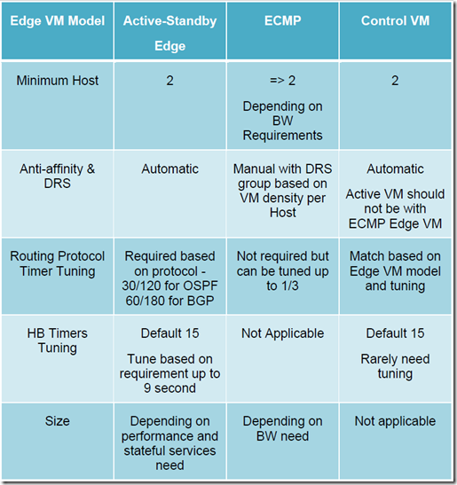
- NSX Manager deploys the pair of NSX Edges on different hosts; anti-affinity rules are automatic
- Heartbeat keepalives are exchanged every second between the active and standby edge instances to monitor each other’s health status
- If the active Edge fails, either due to ESXi server fails or user intervention (e.g., reload, shutdown), at the expiration of a “Declare Dead Time” timer, the standby takes over the active duties
- The default value for this timer is 15 seconds. The recovery time can be improved by reducing the detection time through the UI or API. The minimum value that is supported is 6 seconds
- When the previously active Edge VM recovers on third ESXi host, the existing active Edge VM remains active
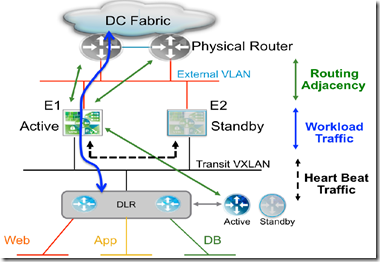
- two uplinks can be enabled from the Edge over which two routing adjacencies establish to two physical routers
- If the active NSX Edge fails (e.g., ESXi host failure), both control and data planes must be activated on the standby unit that takes over the active duties
- HA considerations
- The standby NSX Edge leverages the expiration of a specific “Declare Dead Time” timer to detect the failure of its active peer
- Once the standby is activated, it starts all the services that were running on the failed Edge.
- In order for north-south communication to be successful, it is required that the DLR on the south side of the NSX Edge and the physical router on the north side) start sending traffic to the newly activated Edge
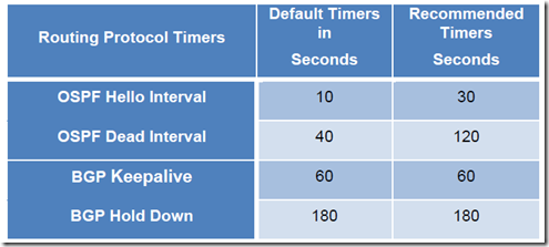
- it is important to consider the impact of DLR active control VM failure to the convergence of workload traffic:
- The DLR Control VM leverages the same active-standby HA model as described for the NSX Edge Services Gateway
- The DLR control-plane active-standby VM also runs a heartbeat timer similar to Edge services VM
- The hold/dead timer setting (e.g., OSPF-120, BGP-180) for the routing timers required between the DLR and the NSX Edge to deal with the NSX Edge failure scenario previously described also allows handling the control VM failure case, leading to a zero seconds outage
- Traffic in the south-to-north direction continues to flow since the forwarding tables in the kernel of the ESXi hosts remain programmed with the original routing information received from the Edge.
- Traffic in the north-to-south direction keeps flowing since the NSX Edge does not time out the routing adjacency with the DLR Control VM established to the “Protocol Address” IP address
- Once the control VM is ready to start sending routing protocol hellos, the graceful-restart functionality on the DLR side comes into the picture to ensure that the NSX Edge can maintain adjacency and continue forwarding the traffic
- ECMP Mode:
- In the ECMP model, the DLR and the NSX Edge functionalities have been improved to support up to 8 equal cost paths in their forwarding tables
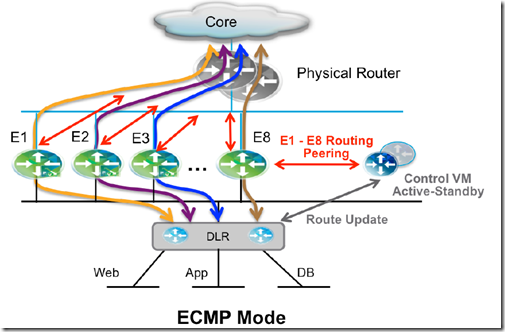
- Advantages:
- An increased available bandwidth for north-south communication, up to 80 Gbps per tenant
- A reduced traffic outage in terms of % of affected flows for NSX Edge failure scenarios
- In this mode, the NSX supports aggressive tuning of the routing hello/hold timers, down to the minimum supported values of 1 second hello and 3 seconds of dead timers on the NSX Edge and the DLR control VM. To achieve lower traffic loss, this is required because the routing protocol hold-time is now the main factor influencing the severity of the traffic outage
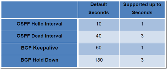
- Considerations
- To maintain minimum availability, at least two ECMP edge VMs are required
- The length of the outage is determined by the speed of the physical router and the DLR control VM timing out the adjacency to the failed Edge VM
- The failure of one NSX Edge now affects only a subset of the north-south flows
- When deploying multiple active NSX Edges, the stateful services cannot be deployed with ECMP mode
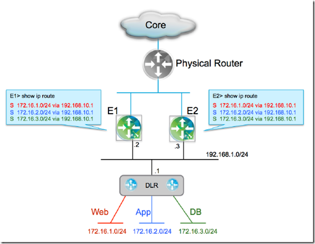
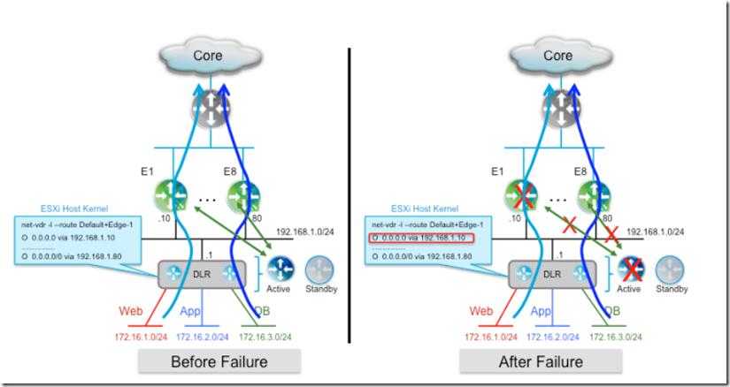
The aggressive setting of routing protocol timers as applied to ECMP mode for faster recovery has an important implication when dealing with the specific failure scenario of the active control VM –> This failure would now cause ECMP Edges to bring down the routing adjacencies previously established with the control VM in less than 3 seconds. To mitigate this failure of traffic, static route with a higher administrative distance than the dynamic routing protocol used between ESG and DLR are needed.
There is no requirement to configure static routing information on the DLR side. If the active control VM fails and the standby takes over and restarts the routing services, the routing information in its forwarding table remains unchanged.
There is an additional important failure scenario for NSX Edge devices in ECMP mode; the failure of the active control VM caused by the failure of the ESXi host where the control VM is deployed together with one of the NSX Edge router.
In this failure event, the control VM cannot detect the failure of the Edge since it has also failed and the standby control VM is still being activated. As a consequence, the routing information in the ESXi host’s kernel still shows a valid path for south-to-north communication via the failed Edge device.This state will exist until the standby control VM is activated, it restarts its routing services, and reestablishes adjacencies with the Edges. This will lead to a long outage for all the traffic flows that are sent via the failed Edge unit.
In order to address this outage:
- Increasing the number of ESXi hosts available in the Edge cluster with anti-affinity rules
- Where there is not enough compute capacity on the Edge cluster, the control VMs can instead be deployed as part of the compute clusters
- Deploying the Control VMs in the management cluster –> small design with collapsed clusters.
Summary:
Differentiate Separate/Collapsed vSphere Cluster topologies
See https://blog.linoproject.net/vcp6-nv-study-notes-section-1-understand-vmware-nsx-technology-and-architecture-part-1/ (Compare and contrast VMware NSX data center deployment models)
Differentiate Layer 3 and Converged cluster infrastructures
Coming soon

[…] For more info click here Spin & Leaf […]