Objective 5.1: Create and Administer Logical Switches
Given a scenario, demonstrate the proper way to add/remove a logical switch and Determine use case for and contrast the three Control Plane Modes
A logical switch is distributed and can span arbitrarily large compute clusters. This allows for virtual machine mobility (vMotion) within the datacenter without limitations of the physical Layer 2 (VLAN) boundary. The physical infrastructure does not have to deal with MAC/FIB table limits since the logical switch contains the broadcast domain in software.
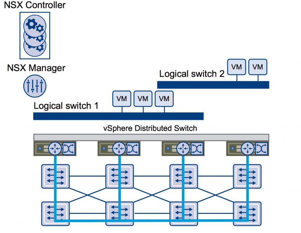
- The NSX controller is the central control point for all logical switches within a network and maintains information of all virtual machines, hosts, logical switches, and VXLANs. It supports the following control planes mode:
- Multicast
- Unicast
- Hybrid
- VXLANs no longer require the physical network to support multicast in order to handle the Broadcast, Unknown unicast, and Multicast (BUM) traffic within a logical switch.
- You can extend a logical switch to a physical device by adding an L2 bridge
- You must have the Super Administrator or Enterprise Administrator role permissions to manage logical switches
Add Procedure:
- Log in to the vSphere Web Client.
- Click Networking & Security and then click Logical Switches.
- Click the New Logical Switch icon.
- Type a name and description for the logical switch.
- Select the transport zone in which you want to create the virtualized network. The Scope Details panel displays the clusters that are part of the selected transport zone and the services available to be deployed on the scope.
- By default, the logical switch inherits the control plane mode from the transport zone. You can change it to one of the other available modes:
- Unicast: The control plane is handled by an NSX controller. All traffic replication is handled locally by the hypervisor. No multicast IP addresses or special network configuration is required.
- Hybrid: The optimized unicast mode. Offloads local traffic replication to physical network. This requires IGMP snooping on the first-hop switch, but does not require PIM. First-hop switch handles traffic replication for the subnet.
- Multicast: Multicast IP addresses on physical network is used for the control plane. This mode is recommended only when you are upgrading from older VXLAN deployments. Requires PIM/IGMP on physical network.
Source: http://pubs.vmware.com/NSX-6/topic/com.vmware.ICbase/PDF/nsx_6_admin.pdf
Determine use case for connecting a logical switch to an NSX Edge gateway
Connecting a Logical Switch to an NSX Edge services gateway or an NSX Edge logical router provides East- West traffic routing (among the logical switches) or North-South traffic routing to the external world or to provide advanced services.
Procedure:
- In vSphere Client Click Networking & Security and then click Logical Switches. Select the logical switch that you want to connect an NSX Edge.
- Click the Add Edge Gateway
- Select the NSX Edge to which you want to connect the logical switch and click Next. Select the interface that you want to connect to the logical switch and click Next.
- A logical network is typically connected to an internal interface.
- On the Edit Edge Gateway Interface page, type a name for the NSX Edge interface. Click Internal or External to indicate wether this is an internal or external interface
- Select the connectivity status of the interface.
- If the NSX Edge to which you are connecting the logical switch has Manual HA Configuration selected, specify two management IP addresses in CIDR format.
- Edit the default MTU if required.
- Click Next and Review the NSX Edge connection details and click Finish.
Source: http://pubs.vmware.com/NSX-6/topic/com.vmware.ICbase/PDF/nsx_6_admin.pdf
Deploy services to a logical switch
You can deploy third party services on a Logical Switch:
- In vSphere Client click Networking & Security and then click Logical Switches.
- Select the logical switch on which you want to deploy services.
- Click the Add Service Profile
- Select the service and service profile that you want to apply and click OK
Source: http://pubs.vmware.com/NSX-6/topic/com.vmware.ICbase/PDF/nsx_6_admin.pdf
Demonstrate multiple ways of adding or removing virtual machines from a logical switch
You can connect virtual machines to a Logical Switch. This makes it easy to identify the port groups that belong to a Logical Switch in your vCenter inventory:
- Login in vSphere Client and click Networking & Security and then click Logical Switches.
- Select the Logical Switch to which you want to add virtual machines
- Click Add
- Select the vNics that you want to connect
- Click Next to Review and Click Finish
Source: http://pubs.vmware.com/NSX-6/topic/com.vmware.ICbase/PDF/nsx_6_admin.pdf
Test logical switch connectivity
A ping test checks if two hosts in a VXLAN transport network can reach each other:
- Login in vSphere Client and Click Networking & Security and then click Logical Switches
- In the Name column, click the logical network that you want to test.
- Click hosts tab and select a host
- Click the “More Actions” icons and select “Test Connectivity”
- Select the size of test packet (standard is 1550 without fragmentation)
- In the destination panel click “Browse Hosts”
- Select destination host in the “Select Host” dialog, click select and click “Start Test”
Source: http://pubs.vmware.com/NSX-6/topic/com.vmware.ICbase/PDF/nsx_6_admin.pdf
Objective 5.2: Configure VXLAN
Describe and understand areas where VXLANs should be configured
You configure VXLAN on a per- cluster basis, where you map each cluster that is to participate in a logical network to a vDS. When you map a cluster to a switch, each host in that cluster is enabled for logical switches. The settings chosen here will be used in creating the VMkernel interface.
Prerequisites:
- All hosts must be connected to vDS
- Network virtualization components must be installed
Procedure:
- Ensure that you are on the Installation > Host Preparation tab
- For the cluster on which you want to configure VXLAN, click Configure in the VXLAN column.
- In the Configuring VXLAN networking dialog box, select the switch to which you want to map the cluster.
- Type the VLAN transport.
- Type the Maximum Transmission Units (MTU) for the virtual distributed switch -> VXLAN traffic frames are slightly larger in size because of encapsulation, so the MTU for each switch must be set to 1550 or higher.
- In VMKNic IP Addressing, specify the IP pool to be used for the Management and Edge cluster:
- use DHCP -> assign IP address to VXLAN VTEPs via DHCP
- use IP pool -> assign a static IP address to VXLAN VTEPs from selected ip pool (or create a new one)
- Select the VMKNic Teaming Policy for the vSwitch. The NIC teaming policy determines the load balancing and failover settings of the virtual switch
- Edit VTEP value if required and click OK
Source: http://pubs.vmware.com/NSX-6/topic/com.vmware.ICbase/PDF/nsx_6_install.pdf
Understand physical network requirements for virtual topologies with VXLANs and Understand how to prepare a vSphere cluster for VXLAN
See above
Determine the appropriate teaming policy for a given implementation
You should choose a teaming policy for VXLAN transport based on the topology of your physical switches.
- It is recommended that you do not mix teaming policies for different portgroups on a vSphere Distributed Switch
- For certain teaming modes, VMware software creates multiple VTEPs to load balance traffic among the physical vNICs.
- Ether channel -> no multiple VTEP created
- Failover -> no multiple VTEP created
- LACPv1 -> no multiple VTEP created. Note: Static Lag and LACP is supported with one VTEP and multiple uplinks.
- LACPv2 -> no multiple VTEP created. Note: Static Lag and LACP is supported with one VTEP and multiple uplinks.
- Source MAC (MAC Hash) -> Multiple VTEP created. Note: Source MAC and Source Port teaming policy will work with one VTEP and one active uplink. You can have multiple uplinks with fail-over policy where the other uplinks are in standby state
Source: http://pubs.vmware.com/NSX-6/topic/com.vmware.ICbase/PDF/nsx_6_install.pdf
Understand how to configure and modify the options of a Transport Zone
A transport zone is the compute diameter defined by a set of vCenter clusters:
- Login in Web Client and click Networking & Security and then click Installation.
- Click Logical Network Preparation and then click Transport Zones.
- Click “New Transport Zone”
- In the New Transport Zone dialog box, type a name and description for the transport zone.
- Depending on whether you have a controller node in your environment, or you want to use multicast addresses, select the control plane mode.
-
Select the clusters to be added to the transport zone and click OK
Source: http://pubs.vmware.com/NSX-6/topic/com.vmware.ICbase/PDF/nsx_6_install.pdf
Objective 5.3: Configure and Manage Layer 2 Bridging
You can create an L2 bridge between a logical switch and a VLAN, which enables you to migrate virtual workloads to physical devices with no impact on IP addresses.
The L2 bridge runs on the host that has the NSX Edge logical router virtual machine. An L2 bridge instance maps to a single VLAN, but there can be multiple bridge instances. The logical router cannot be used as a gateway for devices connected to a bridge.
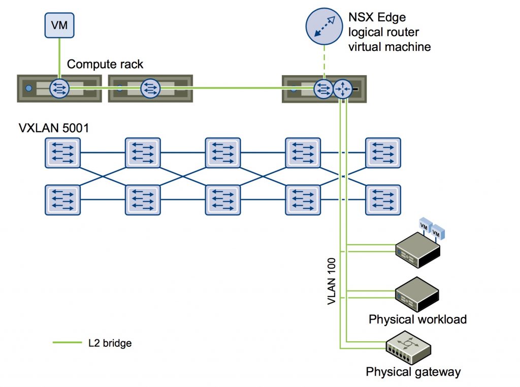
Note: an NSX Logical router must be deployed in order to add L2 Bridge.
Procedure:
- Login in Web Client and click on Network and Security, then click NSX Edge
- Double clcil NSX Edge
- Click Manage and then click Bridging
- Click Add icon and type the name for the bridge
- Select the logical switch that you want to create a bridge for
-
Select the distributed virtual port group that you want to bridge the logical switch to and click OK
Source: http://pubs.vmware.com/NSX-6/topic/com.vmware.ICbase/PDF/nsx_6_admin.pdf