Objective 6.1: Configure and Manage Logical Load Balancing
Describe and understand when to use the two topologies for load balancing
NSX edge LB enables net traffic to pass through multiple paths to a specific destination, to optimal resource optimization. It handles traffic up to L7, mapping eternal (or public) IP address to a set of internal server, accepting
- TCP and UPD (L4 Engine or socket based)
- HTTP or HTTPS (L7 Engine or packet based) (it works with certificates, in order to handle HTTPS connection)
Key concepts:
- Virtual server -> Abstract of an application service, represented by a unique combination of IP, port, and protocol such as TCP or UDP
- Server Pool -> Group of backend servers
- Server Pool Member -> represents the backend server as a member in a pool
- Service Monitor -> Defines how to probe the health status of a backend server.
Understand how to configure load balancing
Procedure to specify global LB config params:
- Click Networking & Security and then click NSX Edges.
- Double click NSX edge and click Manage -> Load balancer tab
- Click Edit and select the option you want to enable:
- Enable Loadbalancer
- Enable service insertion -> allows to work with 3rd party appliances
- Acceleration Enabled -> NSX uses the faster L4 LB rather than L7 LB engine.
- The L4 TCP VIP is processed before the Edge Firewall so no Allow firewall rule is required.
- L7 HTTP/HTTPS VIPs are processed after the Edge Firewall.
- If Enable Acceleration is selected, an Edge Firewall rule must allow access to the L7 HTTP/HTTPS VIP.
- If the Enable Acceleration flag is selected with L4 TCP VIP, and the server pool is in non-transparent mode, an SNAT rule is added. Therefore, make sure that Firewall is enabled on NSX Edge.
- Logging -> enable log collection -> can also configure log level
Configure and understand service monitors
A service monitor defines health check parameters for a particular type of network traffic. Procedure:
- In Networking & Security click NSX Edges, then double-click an NSX Edge.
- Click Manage and then click the Load Balancer tab.
- In the left navigation panel, click Service Monitoring.
- Click the Add icon and type a name for the service monitor.
- Type the interval at which a server is to be pinged.
- Type the maximum time in seconds within which a response from the server must be received.
- Type the number of times the server must be pinged before it is declared down.
- Select the way in which you want to send the health check request to the server.
- For HTTP and HTTPS traffic, perform the steps below:
- Enter the string that the monitor expects to match in the status line of HTTP response in the Expected section. For example, 200,301,302,401.
- Select the method to detect server status from the drop-down menu.
- Enter the URL to be used in the sample request.
- If you select the POST method, enter the data to be sent.
- Enter the string to be matched in the response content in the Receive section.
- Enter advanced monitor parameters as key=value pairs in the Extension section. (see Extension for TCP, HTTP and HTTPS protocols)
- Click OK
Source: https://docs.vmware.com/en/VMware-NSX-for-vSphere/6.2/com.vmware.nsx.admin.doc/GUID-F5546977-F0A6-43E0-89AB-D292C58916CD.html
Understand how to Add/Edit/Delete a server pool
Add Server Procedure:
- In Networking & Security click NSX Edges, then double-click an NSX Edge.
- Click Manage and then click the Load Balancer tab.
- In the left navigation panel, click Pools and type a name and description for the load balancer pool.
- Select a balancing method for each enabled service.
- IP_HASH -> select a server based on source and destination IP address of each packet
- LEAST_CONN -> distributes client requests to multiple servers based on number of connection already on server.
- ROUD_ROBIN -> each server is used in turn according to the weight assigned to it.
- URI -> the part of the URI before question mark (left part), is hashed and divided by the total weight of the running servers -> ensures that a URI is always directed to the same server as long as the server goes up or down.
- HTTPHEADER -> HTTP header name is looked up in each HTTP request.
- URL -> URL parameter specified in the argument is looked up in the query string of each HTTP GET request. If no value or parameter is found, then a round robin algorithm is applied.
- (Optional) : Select an existing default or custom monitor from the Monitors drop-down menu.
- Add members to the pool.
- Click the Add icon.
- Type the name and IP address of the server member.
- Type the port where the member is to receive traffic on and the monitor port where the member is to receive health monitor pings.
- In Weight, type the proportion of traffic this member is to handle.
- Type the maximum number of connections the member can handle.
- Type the minimum number of connections a member should handle before traffic is redirected to the next member.
- Click OK.
- Transparent indicates whether client IP addresses are visible to the backend servers. If Transparent is not selected (default value), backend servers see the traffic source IP as a Load balancer internal IP. If Transparent is selected, source IP is the real client IP and NSX Edge must be set as the default gateway to ensure that return packets go through the NSX Edge device.
- Click OK
Edit refer to https://docs.vmware.com/en/VMware-NSX-for-vSphere/6.2/com.vmware.nsx.admin.doc/GUID-B44DCA5B-73E6-4C10-A2D1-F01976495F28.html
Delete refer to https://docs.vmware.com/en/VMware-NSX-for-vSphere/6.2/com.vmware.nsx.admin.doc/GUID-4C3A06B8-4B80-4F1E-8139-95E6B7FDE70A.html
Understand how to Add/Edit/Delete an application profile
You create an application profile to define the behavior of a particular type of network traffic.
- In Networking & Security click NSX Edges, then double-click an NSX Edge.
- Click Manage and then click the Load Balancer tab.
- In the left navigation panel, click Application Profiles.
- Click the Add and type a name for the profile and select the traffic type for which you are creating the profile from the drop-down menu:
- TCP -> persistence method supported Source IP, MSRDP
- HTTP -> persistence method supported Cookie, Source IP
- HTTPS -> persistence method supported Cookie, SSL Session ID (if SSL Passthrough enabled, Source IP)
- UDP -> persistence method supported Source IP
- Type the URL to which you want to redirect HTTP traffic
- Specify persistence type for the profile:
- Cookie
- Source IP
- MSRDP
- Type a cookie name and select mode which the cookie should be inserted:
- Insert -> NSX Edge sends a cookie
- Prefix -> This option is selected if your client does not support more than one cookie.
- App Session -> The server does not send a cookie. Instead, it sends the user session information as a URL.
- Enter the persistence expiration time in seconds (default 5min). For the L7 load balancing TCP source IP persistence scenario, the persistence entry times out if no new TCP connections are made for a period of time, even if the existing connections are still alive.
- Optionally create an application profile for HTTPS traffic:
- SSL Offloading – Client -> HTTPS -> LB (terminate SSL) -> HTTP -> server
- SSL Proxy – Client -> HTTPS -> LB (terminate SSL) -> HTTPS -> server
- SSL Passthrough – Client -> HTTPS-> LB (SSL passthrough) -> HTTPS -> server
- Client -> HTTP-> LB -> HTTP -> servers
- (Optional) : Check Insert X-Forwarded-For HTTP header
- Check Configure Service Certificate to select the applicable service certificate, CA certificates, and CRLs used to terminate the HTTPS traffic from the client on the load balancer in the Virtual Server Certificates tab.
- Check Configure Service Certificate to select the applicable service certificate, CA certificates, and CRLs used to terminate the HTTPS traffic from the client on the load balancer in the Virtual Server Certificates tab.
- (Optional) : Check Enable Pool Side SSL to enable the HTTPS communication between the load balancer and the backend servers.
- (Optional) : Check Configure Service Certificate to select the applicable service certificate, CA certificates, and CRLs used to authenticate the load balancer from the server side in the Pool Certificates tab.
- Enter the cipher algorithms or cipher suite negotiated during the SSL/TLS handshake.
- Specify whether client authentication is to be ignored or required from the drop-down menu.
- Click OK
Edit refer to https://docs.vmware.com/en/VMware-NSX-for-vSphere/6.2/com.vmware.nsx.admin.doc/GUID-72399589-46BD-4CA2-8448-7A8844F78842.html
Delete refer to https://docs.vmware.com/en/VMware-NSX-for-vSphere/6.2/com.vmware.nsx.admin.doc/GUID-544A5B45-E2AE-416C-814B-F79D1CE13065.html
Understand how to Add/Edit/Delete virtual servers
Prerequisites:
- Application profile is available.
- If you are associating an application rule with the virtual server
- If you are enabling acceleration to use the faster load balancer, the acceleration should be enabled when configuring the load balancer. See Configure Load Balancer Service.
Procedure:
- Log in to the vSphere Web Client.
- In Networking & Security click NSX Edges, then double-click an NSX Edge.
- Click Manage and then click the Load Balancer tab.
- In the left navigation panel, click Virtual Servers.
- Click the Add icon
- Check Enable Virtual Server to make this virtual server available for use.
- (Optional) : Check Enable Acceleration for the NSX Edge load balancer to use the faster L4 load balancer engine rather than L7 load balancer engine.
- Select the application profile to be associated with the virtual server. You can associate only an application profile with the same protocol as the virtual server that you are adding. The services supported by the selected pool appear.
- Enter a name and description for the virtual server.
- Click Select IP Address to set the IP address that the load balancer is listening on and type the protocol that the virtual server will handle.
- Select the protocol that the virtual server handles from the drop-down menu.
- Enter the port number that the load balancer listens on. Can also set a range of ports (80, 8001-8004, 443). To use FTP, the TCP protocol must have port 21 assigned to it.
- Select the application rule.
- Enter the maximum concurrent connections that the virtual server can process in the Connection Limit section.
- Enter the maximum incoming new connection requests per second in the Connection Rate Limit section.
- (Optional) : Click the Advanced tab and add the application rule to associate it with the virtual server.
- Click OK.
Edit refer to https://docs.vmware.com/en/VMware-NSX-for-vSphere/6.2/com.vmware.nsx.admin.doc/GUID-FD567442-40A4-4BCB-B611-54A1C8474954.html
Delete refer to https://docs.vmware.com/en/VMware-NSX-for-vSphere/6.2/com.vmware.nsx.admin.doc/GUID-F2182944-E1F2-4D84-9D07-88679C019BC7.html
Objective 6.2: Configure and Manage Logical Virtual Private Networks (VPN)
NSX Edge supports several types of VPNs:
- SSL VPN-Plus allows remote users to access private corporate applications.
- IPSec VPN offers site-to-site connectivity between an NSX Edge instance and remote sites.
- L2 VPN allows you to extend your datacenter by allowing virtual machines to retain network connectivity across geographical boundaries.
Understand how to configure IPSec VPN
Procedure:
- Use OpenSSL to Generate CA-Signed Certificates for IPSec VPNs
- On a Linux or Mac machine where OpenSSL is installed, open the file: /opt/local/etc/openssl/openssl.cnf or /System/Library/OpenSSL/openssl.cnf and ensure that dir=..
- Issue the following commands:
- mkdir newcerts
- mkdir certs
- mkdir req
- mkdir private
- echo “01” > serial
- touch index.txt
- Run the command to generate CA-signed certificate: openssl req -new -x509 -newkey rsa:2048 -keyout private/cakey.pem -out cacert.pem -days 3650
- On NSX Edge1, generate a CSR, copy the privacy-enhanced mail (PEM) file content, and save it in a file in req/edge1.req.
- Run the command to sign CSR: sudo openssl ca -policy policy_anything -out certs/edge1.pem -in req/edge1.req
- On NSX Edge2 enerate a CSR, copy the PEM file content, and save it in a file in req/edge2.req.
- Run the command to sign CSR: sudo openssl ca -policy policy_anything -out certs/edge2.pem -in req/edge2.req
- Upload the PEM certificate at the end of the file certs/edge1.pem to Edge1 and certs/edge2.pem to Edge2.
- Upload the CA certificate in the file cacert.pem to Edge1 and Edge2 as CA-signed certificates.
- In the IPSec global configuration for Edge1 and Edge2, select the uploaded PEM certificate and the uploaded CA certificate and save the configuration.
- On the Certifcate tab, click the uploaded certificate and record the DN string.
- Reverse the DN string to the format C=IN,ST=ka,L=blr,O=bmware,OU=vmware,CN=edge2.eng.vmware.com and save it for Edge1 and Edge2.
- Create IPsec VPN sites on Edge1 and Edge2 with Local ID and Peer ID as the distinguished name (DN) string in the specified format.
- Specify Global IPSec VPN Configuration
- Click IPSec VPN.
- Click Change next to Global configuration status.
- Type a global pre-shared key for those sites whose peer endpoint is set to any and select Display shared key to display the key.
- Select Enable certificate authentication and select the appropriate certificate.
- Click OK
- Enable Logging for IPSec VPN
- Click IPSec VPN.
- Click next to Logging Policy and click Enable logging to log the traffic flow between the local subnet and peer subnet and select the logging level.
- Select the log level and click Publish Changes.
- Configure IPSec VPN Parameters
- Click IPSec VPN.
- Click the Add icon.
- Type a name for the IPSec VPN.
- Type the IP address of the NSX Edge instance in Local Id. This will be the peer Id on the remote site.
- Type the IP address of the local endpoint. If you are adding an IP to IP tunnel using a pre-shared key, the local Id and local endpoint IP can be the same.
- Type the subnets to share between the sites in CIDR format. Use a comma separator to type multiple subnets.
- Type the Peer Id to uniquely identify the peer site. For peers using certificate authentication, this ID must be the common name in the peer’s certificate. For PSK peers, this ID can be any string. VMware recommends that you use the public IP address of the VPN or a FQDN for the VPN service as the peer ID.
- Type the IP address of the peer site in Peer Endpoint. If you leave this blank, NSX Edge waits for the peer device to request a connection.
- Type the internal IP address of the peer subnet in CIDR format. Use a comma separator to type multiple subnets.
- Select the Encryption Algorithm.
- In Authentication Method, select one of the following:
- PSK (Pre Shared Key)
- Certificate
- Type the shared key in if anonymous sites are to connect to the VPN service.
- Click Display Shared Key to display the key on the peer site.
- In Diffie-Hellman (DH) Group, select the cryptography scheme that will allow the peer site and the NSX Edge to establish a shared secret over an insecure communications channel.
- In Extension, type one of the following:
- ecurelocaltrafficbyip=IPAddress to re-direct Edge’s local traffic over the IPSec VPN tunnel. This is the default value.
- passthroughSubnets=PeerSubnetIPAddress to support overlapping subnets .
- Click OK
- Enable IPSec VPN ServiceClick the Manage tab and then click the VPN tab.
- Click IPSec VPN
- Click Enable
Understand how to configure Layer 2 VPN
L2 VPN allows you to configure a tunnel between two sites. Virtual machines remain on the same subnet in spite of being moved between these sites, which enables you to extend your datacenter. An NSX Edge at one site can provide all services to virtual machines on the other site.
Procedure:
- Configuring L2 VPN
- L2 VPN Best Practices. Configuring L2 VPN according to best practices can avoid problems such as looping and duplicate pings and responses.
- Configure L2 VPN Server. The L2 VPN server is the destination NSX Edge to which the client is to be connected.
- Add Peer Sites. You can connect multiple sites to the L2 VPN server.
- Enable L2 VPN Service on Server. You must enable the L2 VPN service on the L2 VPN server (destination NSX Edge). If HA is already configured on this Edge appliance, ensure that Edge has more than one internal interface configured on it. If only a single interface is present and that has already been used by HA, L2 VPN configuration on the same internal interface will fail.
- Configure L2 VPN Client. The L2 VPN client is the source NSX Edge that initiates communication with the destination Edge (L2 VPN server).
- Enable L2 VPN Service on Client. You must enable the L2 VPN service on the L2 VPN client (source NSX Edge).
- Configure Standalone Edge as L2 VPN Client
- View L2 VPN Statistics
Further informations and procedures: https://docs.vmware.com/en/VMware-NSX-for-vSphere/6.2/com.vmware.nsx.admin.doc/GUID-7977542E-C4BA-484A-9811-1233E2401A23.html
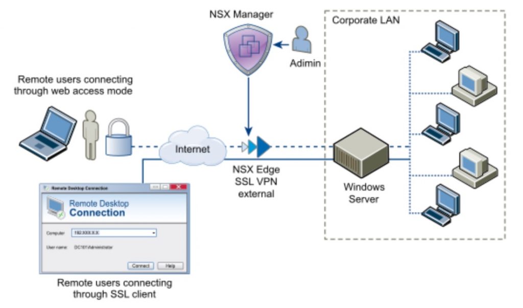
Configure Network Access/Web Access SSL VPN-Plus
With SSL VPN-Plus, remote users can connect securely to private networks behind a NSX Edge gateway. Remote users can access servers and applications in the private networks.
Supported clients:
- Windows XP and above (Windows 8 is supported).
- Mac OS X Tiger, Leopard, Snow Leopard, Lion, Mountain Lion, Maverick, and Yosemite. These can be installed either manually or using the Java installer.
- Linux – TCL-TK is required for UI to work. If not present, Linux client can be used using CLI.
Workflow:
- Configure Network Access SSL VPN-Plus
- Add SSL VPN-Plus Server Settings.
- Add an IP Pool.
- Add a Private Network.
- Add Authentication: local user, external auth (AD, LDAP, Radius, or RSA) which is bound to the SSL gateway
- Add Installation Package
- Add a User
- Enable the SSL VPN-Plus Service
- Add a Script
- Install SSL Client on Remote Site
- Configure Web Access SSL VPN-Plus
- Create a Web Resource
- Add a User
- Add Authentication: local user, external auth (AD, LDAP, Radius, or RSA) which is bound to the SSL gateway
- Add SSL VPN-Plus Server Settings
- Enable the SSL VPN-Plus Service
- Add a Script
- SSL VPN-Plus Logs.
- Edit Client Configuration
- Edit General Settings
- Edit Web Portal Design
- Working with IP Pools
- Working with Private Networks
- Working with Installation Packages
- Working with Users
- Working with Login and Logoff Scripts
Further info and procedure here: https://docs.vmware.com/en/VMware-NSX-for-vSphere/6.2/com.vmware.nsx.admin.doc/GUID-160E1FF2-7C96-4575-AA8C-3E7962AE22E5.html
Determine appropriate VPN service type for a given NSX implementation
See Above